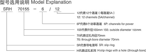
SRH70155
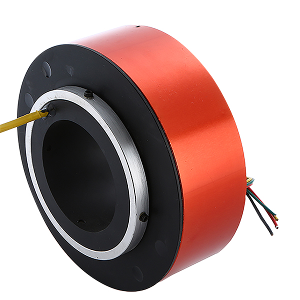
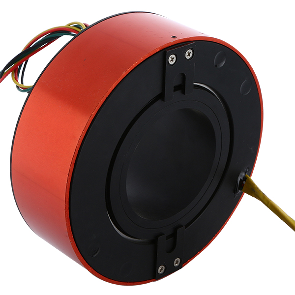
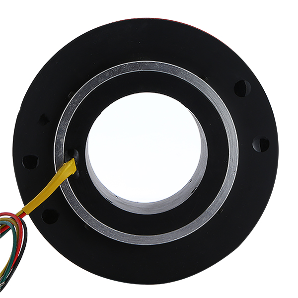
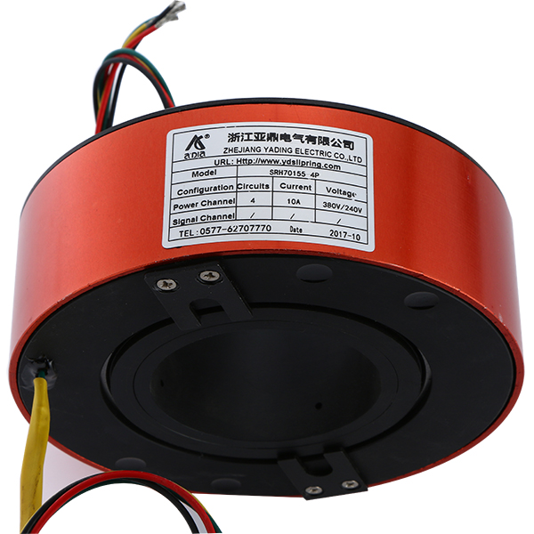
Series SRH70155
Electrical Technique Indicators
|
Parameters |
Value |
|
|
Power |
Signal |
|
|
Nominal Voltage |
380VAC |
240VAC/VDC |
|
Insulation Resistance |
≥1000MΩ/500VDC |
≥500MΩ/500VDC |
|
Conductor Size |
AWG16 Tin-plated Teflon or PVC insulation wires |
AWG22 Tin-plated Teflon Insulation wires |
|
Conductor Length |
Standard 300mm |
|
|
Insulation strength |
500VAC@50Hz,60s |
|
|
Electrical Noise |
<0.01Ω |
|
Mechanical Technique Indicators
|
Parameters |
Value |
|
|
Power |
Signal |
|
|
Working Speed |
0~500 rpm |
|
|
Working Temperature |
-20℃ - +80℃ |
|
|
Working Humidity |
60%RH or higher |
|
|
Contact Material |
Nobel Metal |
|
|
Casting Material |
Aluminium Alloy |
|
|
Torque |
0.1N/m for 6 rings, the torque increases by 0.03 N/m with each 6 rings |
|
|
Protection Class |
IP51 |
|
Specification Table
|
Type |
Length(L=mm) |
Nominal Voltage |
Ring Number |
|
|
Power(10A/15A/20A) |
Signal(5A) |
|||
|
SRH70155-6P |
71 |
6 |
— |
6 |
|
SRH70155-12S |
95 |
— |
12 |
12 |
|
SRH70155-12P |
95 |
12 |
— |
12 |
|
SRH70155-6P/12S |
119 |
6 |
12 |
18 |
|
SRH70155-24S |
143 |
— |
24 |
24 |
|
SRH70155-18P |
119 |
18 |
— |
18 |
|
SRH70155-12P/12S |
143 |
12 |
12 |
24 |
|
SRH70155-6P/24S |
167 |
6 |
24 |
30 |
|
SRH70155-36S |
191 |
— |
36 |
36 |
|
SRH70155-24P |
143 |
24 |
— |
24 |
|
SRH70155-18P/12S |
167 |
18 |
12 |
30 |
|
SRH70155-12P/24S |
191 |
12 |
24 |
36 |
|
SRH70155-6P/36S |
215 |
6 |
36 |
42 |
|
SRH70155-48S |
239 |
— |
48 |
48 |
|
SRH70155-30P |
167 |
30 |
— |
30 |
|
SRH70155-24P/12S |
191 |
24 |
12 |
36 |
|
SRH70155-18P/24S |
215 |
18 |
24 |
42 |
|
SRH70155-12P/36S |
239 |
12 |
36 |
48 |
|
SRH70155-6P/48S |
263 |
6 |
48 |
54 |
|
SRH70155-60S |
287 |
— |
60 |
60 |
|
SRH70155-36P |
191 |
36 |
— |
36 |
|
SRH70155-30P/12S |
215 |
30 |
12 |
42 |
|
SRH70155-24P/24S |
239 |
24 |
24 |
48 |
|
SRH70155-18P/36S |
263 |
18 |
36 |
54 |
|
SRH70155-12P/48S |
287 |
12 |
48 |
60 |
|
SRH70155-6P/60S |
311 |
6 |
60 |
66 |
|
SRH70155-72S |
335 |
— |
72 |
72 |
|
SRH70155-42P |
215 |
42 |
— |
42 |
|
SRH70155-36P/12S |
239 |
36 |
12 |
48 |
|
SRH70155-30P/24S |
263 |
30 |
24 |
54 |
|
SRH70155-24P/36S |
287 |
24 |
36 |
60 |
|
SRH70155-18P/48S |
311 |
18 |
48 |
66 |
|
SRH70155-12P/60S |
335 |
12 |
60 |
72 |
|
SRH70155-6P/72S |
359 |
6 |
72 |
78 |
|
SRH70155-84S |
153 |
— |
84 |
84 |
|
SRH70155-48P |
239 |
48 |
— |
48 |
|
SRH70155-42P/12S |
263 |
42 |
12 |
54 |
|
SRH70155-36P/24S |
287 |
36 |
24 |
60 |
|
SRH70155-30P/36S |
311 |
30 |
36 |
66 |
|
SRH70155-24P/48S |
335 |
24 |
48 |
72 |
|
SRH70155-18P/60S |
359 |
18 |
60 |
78 |
|
SRH70155-12P/72S |
383 |
12 |
72 |
84 |
|
SRH70155-6P/84S |
407 |
6 |
84 |
90 |
|
SRH70155-96S |
431 |
— |
96 |
96 |
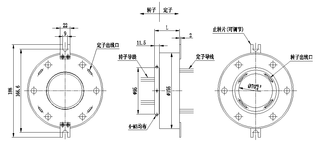
Shape dimension figure
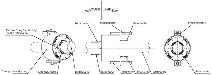
Installation
Instruction
Due to the difficulty of creating concentric installation of the rotors and stators of the slip rings, it’s advised to fix the slip rings to the rotation shaft with four fastening screws and to fix the stop plate into the stop rod. Forcible operations of the stop plate may reduce the anticipated service life of the slip rings.
Notes
1. The rings should bear no weights, and the conductors should bear no external forces.
2. The conductors should be well protected to avoid damage of the insulating layer and malfunction of the product in installation.
3. Slip rings are precision electrical equipments and should be placed in dry and dust-free environment. Precautions should be taken in harsh situations.
