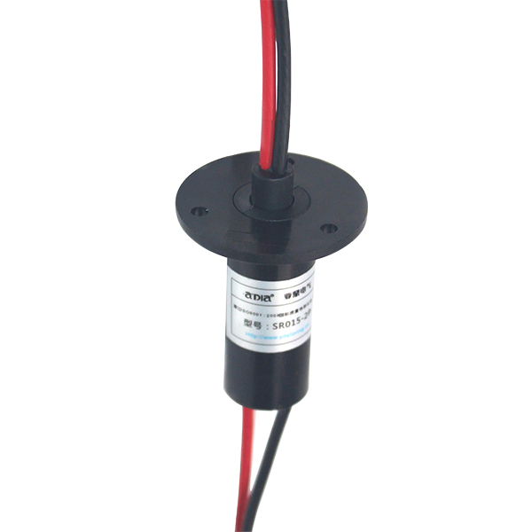
Capsule Slip Ring SRC015

Features and Applications
Conductive slip rings, applied in slip connection with electricity, and widely referred to as collector rings, rotary joints, rotating electrical interfaces, slip rings, current collectors, coils, steering gears and adaptors, serve as power transmission devices for data, signals and power between two rotating mechanisms. Specially adopted in unlimited continual rotation, they also provide transmission of the power and data between the position point and the rotation point.
It consists elastic materials-electrical brushes, sliding contacts-and conducting rings, insulating materials, binding materials, composite stands, precision bearings, dust covers as well as other auxiliary components. The electrical brushes are made of noble metal with superior insulation function, and are symmetrically connected to grooves of the conductive slip rings on both ends in a “II” shape, thus transmitting signals and current through the elastic stress of the brush and the sliding contact of the groove. As a major component in precise rotating platforms, centrifugal machines and inertial navigation equipments, it is widely adopted in electromechanical devices in security, factory automation, power, finance, instruments, chemical engineering, metallurgy, medical treatment, aviation, military, shipping, transportation, architecture and other sectors.
Order model description

Electrical Technique Indicators
|
Parameters |
Value |
|
Nominal Voltage |
240VDC/240VAC |
|
Rated Current |
2A per ring |
|
Conductor Size |
Teflon AWG30# silver plated |
|
Conductor Length |
250mm or as required by the clients |
|
Insulation strength |
500VAC@50Hz,60s |
|
Insulation Resistance |
1000MΩ/500VDC |
|
Electrical Noise |
<0.01Ω |
Mechanical Technique Indicators
|
Parameters |
Value |
|
Working Speed |
0~300rpm |
|
Working Temperature |
-20℃-+80℃ |
|
Working Humidity |
60%RH or higher |
|
Contact Material |
Nobel Metal |
|
Casting Material |
Engineering Plastics |
Specification Table
|
Type |
Loop Number |
Maximum current per channel |
Wire specifications |
Length |
|
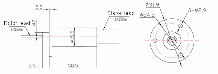
SRC015-02 |
6 |
1.5A |
Teflon AWG30# silver plated |
38.5 |
|
SRC015-06 |
12 |
1.5A |
Teflon AWG30# silver plated |
14 |
|
SRC015-12 |
12 |
5A |
Teflon AWG30# silver plated |
19.5 |
Color Chart for Conductors
|
SRC012-6 |
1. Red |
2. Yellow |
3. Black |
4.Blue |
5.Green |
6. White |
|
|
SRC012-8 |
1.Black |
2.Brown |
3. Red |
4.Orange |
5. Yellow |
6. Green |
|
|
7. Blue |
8. Purple |
|
|||||
|
SRC012-12 |
1. Red |
2. Green |
3. Yellow |
4. Purple |
5. Gray |
6.Black |
|
|
7. Blue |
8.Deep blue |
9.Brown |
10.Orange |
11.White |
12.Earthy |
||
|
SRC012-15 |
1. Red |
2.Green |
3.Yellow |
4.Purple |
5.Gray |
6.Black |
|
|
7. Blue |
8.Deep blue |
9.Brown |
10.Orange |
11.White |
12.Earthy |
||
|
13.White-Red |
14.White-Black |
15.White-Blue |
|
||||
|
SRC012-18 |
1. Red |
2. Green |
3. Yellow |
4.Purple |
5.Gray |
6. Black |
|
|
7. Blue |
8.Deep blue |
9.Brown |
10.Orange |
11.White |
12. Earthy yellow |
||
|
13.White-Red |
14.White-Black |
15.White-Blue |
16.White-Purple |
17.White-Brown |
18.White-Green |
||
SRC015 Series /C Type Flanges

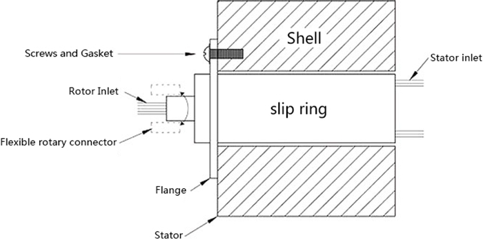
Installation Instructions
1. The slip rings should be fixed on telescope-feed brackets.
2. The rotors should be concentrically driven by the rotor leads at specific speed with flexile connectors.

As is shown in the picture, screws with gaskets should be applied in the installation to avoid being unduly flanged.

Notes:
1. The rings should bear no weights, and the conductors should bear no external forces.
2. The conductors should be well protected to avoid damage of the insulating layer and malfunction of the product in installation.
3. Slip rings are precision electrical equipments and should be placed in dry and dust-free environment. Precautions should be taken in harsh situations.
